1) Number of Cable Conductors.
The 1512 / 2512 Pipe Profiling Sonar's require 4 conductors in the connecting cable from the underwater scanner unit to the USB or Ethernet Interface Unit.
2 are required for power and 2 for data communication
2) Power Conductors
For the DC power conductors the lower the cable resistance the longer the cable run. The underwater sonar unit draws around 0.5 amps and for the model 1512 USB the minimum DC voltage at the scanner end should be +26V DC whereas for the 1512 Ethernet this reduces to +24V DC. The 2512 requires a minimum of +14V DC supply at the scanner. To calculate the required voltage measure the DC resistance of the 2 power cores and then use Ohm's Law to calculate the voltage drop. ( V=IR where V=Voltage Drop, I=Current, R=DC Resistance ). ( i.e. If the cable is 5 ohms per conductor then the voltage drop V = 0.5 x 10 = 5v. Thus to achieve +26v at the scanner will require +31v DC )
3) Data Conductors
The data conductors should be either a coaxial cable or fully screened twisted pair. As the data signal is the amplified 2MHz receive envolope the length of cable will be limited by the bandwidth. For up to 500m cable length a coaxial cable type RG59 or equivalent is suitable but for lengths up to 1000m type RG213 is recommended
4) Data Format
The analogue sonar data uplink characteristics are a nominal level of 0v DC with negative going sync pulses ( one for each ping i.e. 400 per revolution with a pulse width equal
to the transmit pulse length setting i.e. 2usec to 20usec ) then the sonar echo return is a positive going envolope of the 2MHz acoustic signal. The unloaded voltage for the sonar
signal is up to +/- 10v DC but once terminated will reduce to around +/- 4v DC.
The digital communications that controls the sonar head plus transmission of the pitch and roll data is an RS232 9600 baud signal utilising the same link as the sonar data.
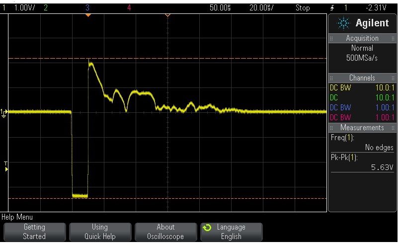
Above pictue of the 1512 data comms showing negative sync pulse followed by 2MHz Transmit Breakthrough.
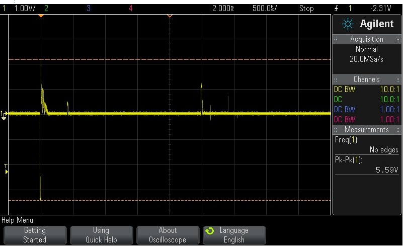
Above pictue of the 1512 data comms showing 1 of the 400 steps per revolution of the transducer.
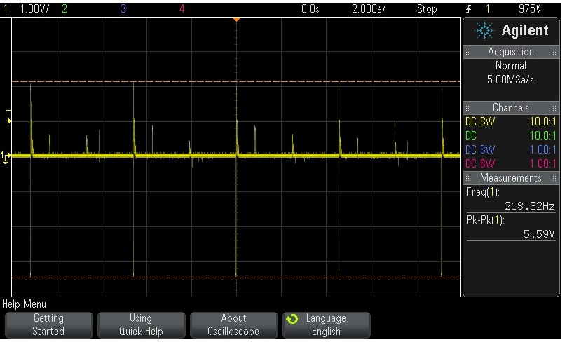
Above pictue of the 1512 data comms showing 5 of the 400 steps per revolution of the transducer.
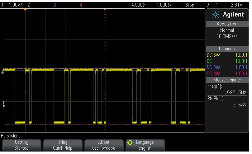
Above pictue of the 1512 command comms showing negative RS232 pulses.
5) Power Supply
The DC power supply for the 1512 and 2512 should be floating and not connected to any other supply. If the system has not been supplied with a USB Interface Unit that includes an AC to variable DC supply then a suitable DC supply will be required. The supply should be capable of a minimum output current of 1 amp and voltage adjustable from +26v to +36v for the 1512 and between +14v and +24v for the 2512.